Top 10 Types of 3 Phase 400Hz Frequency Converters?

A 3 phase 400hz frequency converter is more than a frequency-changing box. It is a controlled power source for aircraft systems, aerospace test benches, military electronics, and specialized industrial equipment. Many applications require clean 400 Hz power, often at 115/200 volts, with stable phase relationships and low distortion.

This guide examines the top 10 types of 3 phase 400hz frequency converter, including rotary converters, static converters, AC-DC-AC systems, motor-generator sets, and programmable laboratory units. Each design behaves differently under real operating conditions. A compact static converter may fit beside a test rack, while a rotary unit may require floor space, ventilation, and regular bearing checks. Input frequency, output voltage, load balance, isolation, cooling, and transient response all influence the final choice.

Dr. Ned Mohan, a respected power-electronics educator and author, states, “Power electronics is the technology of controlling and converting electrical energy.” That principle remains useful here. A converter should be judged by the complete electrical system, not by its nameplate alone. Engineers should check waveform quality with measurement equipment, especially when sensitive avionics or motors are connected. Small assumptions can become expensive faults.

No single converter type wins every project. That is the uncomfortable part. Rotary equipment can be robust, yet noisy. Static equipment is efficient, yet sensitive to heat and harmonics. Some categories also overlap, which can make comparisons imperfect. This introduction provides a practical starting point for evaluating performance, maintenance, safety, and long-term reliability.
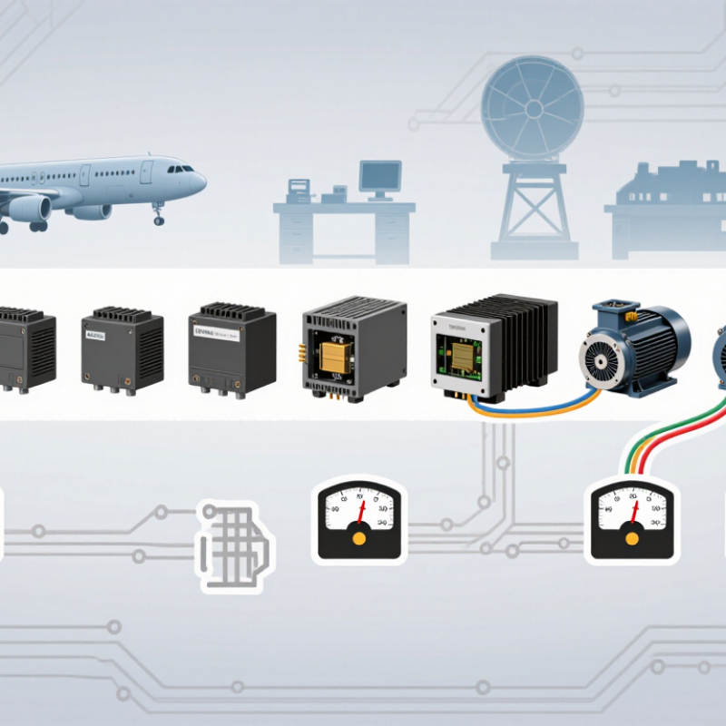
Top 10 Types of 3 Phase 400Hz Frequency Converters?

400 Hz Power Fundamentals: 8× 50 Hz and 6.67× 60 Hz

A 400 Hz converter begins with a simple frequency relationship. Eight cycles of 50 Hz produce 400 Hz exactly. At 60 Hz, 6.67 cycles produce approximately 400.2 Hz, not perfect 400 Hz. The converter must synthesize the missing fraction electronically. That small error matters in aircraft test benches, radar systems, and precision motor drives.

The ten common categories include static frequency converters, rotary converters, motor-generator sets, digital converters, regenerative units, bidirectional units, isolated converters, modular systems, mobile units, and rack-mounted systems. Static and digital designs usually provide tighter frequency control. Rotary equipment can offer strong overload performance, but it needs more maintenance. The U.S. Federal Aviation Administration’s Aerospace Forecast 2024–2044 expects continued aviation activity and fleet growth, supporting long-term demand for reliable 400 Hz ground power. IATA’s 2024 passenger forecast estimated 4.96 billion air travelers, increasing pressure on airport support equipment.

Selection should follow load behavior, not frequency alone. A 400 Hz induction motor may require controlled acceleration and low harmonic distortion. Sensitive avionics may need isolation, voltage regulation, and fast fault protection. The International Energy Agency reports that motor-driven systems consume roughly half of global electricity, showing why converter efficiency deserves attention. Still, published efficiency figures often reflect ideal loads. Real installations face heat, cables, altitude, and uneven loading. That shortcut is useful, but imperfect.

Top 10 Three-Phase Converter Types for 115/200 V and 400 Hz Systems

For 115/200 V, 400 Hz systems, converter selection begins with the load, not the enclosure. The 115 V phase-to-neutral and approximately 200 V phase-to-phase relationship follows a three-phase wye configuration. MIL-HDBK-704-3 identifies these aircraft power characteristics as key design references. RTCA DO-160G Section 16 also evaluates input-power variation, frequency shifts, and transients. These requirements make ten converter families especially relevant: rotary motor-generators, static PWM inverters, resonant inverters, matrix converters, cycloconverters, AC-DC-AC converters, DC-link inverters, bidirectional regenerative converters, variable-frequency converters, and modular parallel converters.

Rotary units tolerate harsh environments and can provide strong short-term overload performance. They are heavy, though. Static PWM converters are smaller and easier to monitor, while resonant designs can reduce switching losses and acoustic noise. Matrix converters avoid a large energy-storage capacitor, but control software becomes demanding.

Cycloconverters suit specialized frequency conversion, yet their waveform quality may require filtering. AC-DC-AC and DC-link designs offer flexible isolation, protection, and regulation.

Bidirectional converters support regenerative loads, such as motor-driven test benches. Variable-frequency units help simulate changing aircraft generators. Modular parallel systems improve serviceability and capacity growth.

Keep margins. A converter rated exactly at the measured load may fail during startup or fault recovery. Published test standards improve reliability, but field installation still matters. Cable length, grounding, cooling airflow, and harmonic interaction can alter results. Some early selections look efficient on paper, then disappoint during thermal testing. Recheck the assumptions.

Static, Rotary, and Solid-State Designs: Comparing 90–98% Efficiency

Three-phase 400 Hz frequency converters generally fall into ten practical types: transformer-rectifier-inverter, PWM static converter, matrix converter, cycloconverter, resonant converter, modular multilevel converter, regenerative converter, bidirectional converter, motor-generator set, and rotary frequency converter. Static and solid-state designs usually occupy less space, while rotary units tolerate harsh overloads better. The U.S. Department of Energy reports that modern adjustable-speed drive systems can reach roughly 95–98% efficiency under suitable operating conditions (Improving Motor and Drive System Performance, 2014). Real results vary.

Efficiency is not constant. A 400 Hz PWM converter may approach 98% near rated load, but cooling fans, transformers, filters, and standby losses reduce system efficiency. Rotary motor-generator sets often operate near 90–95%, especially when lightly loaded.

Solid-state designs can provide faster control and cleaner output, yet switching losses and harmonic filters demand careful engineering. IEEE 519-2022 highlights the importance of controlling harmonic distortion at the point of common coupling. A neat ranking is tempting, but it can mislead. Load profile matters more than the brochure figure.

Tips: Measure efficiency at 25%, 50%, 75%, and 100% load. Check heat rise, input power factor, acoustic noise, and output waveform. For aircraft or test-bench equipment, verify 400 Hz stability during sudden load changes. Do not compare converter percentages without matching cooling, filter, and transformer conditions. That comparison is often unfair.

Sizing Converter Capacity: 100 kVA at 115/200 V Draws About 289 A

Top 10 Types of 3 Phase 400Hz Frequency Converters

When sizing a 400Hz frequency converter, capacity and voltage must match the aircraft, test system, or industrial load. A 100 kVA converter delivering 115/200 V three-phase power supplies about 289 A at 200 V line-to-line. The calculation is simple: 100,000 divided by 1.732 and 200. The 115 V value describes each phase to neutral. It does not replace the line-to-line voltage in this calculation.

The 289 A figure represents an ideal load. Real systems need additional attention. Converter efficiency, power factor, motor starting current, cable temperature, and altitude can increase the required capacity. A converter operating continuously near its limit may also run hotter than expected. In field reviews, a common mistake is selecting capacity from steady-state current alone. That approach looks reasonable, but it can fail during startup. I would normally allow practical headroom, then confirm the manufacturer’s output-current curve and duty rating. The final choice should follow measured load behavior, not guesswork.

Tips: Confirm whether the load is balanced. Check peak current with a true-RMS meter. Keep voltage-drop calculations visible. Do not assume input current equals output current. Record ambient temperature, cable length, and startup conditions before choosing the next converter size.

Top 10 Three-Phase 400 Hz Frequency Converter Capacity Examples

Estimated line current for 115/200 V, three-phase systems. Current is calculated from I = S ÷ (√3 × VLL), assuming unity power factor and 100% efficiency.

A 100 kVA converter at 200 V line-to-line draws approximately 289 A: 100,000 ÷ (1.732 × 200) ≈ 288.7 A. Actual input current may be higher because of efficiency, power factor, harmonics, and transient loading.

Selection Standards: MIL-STD-704, IEC 61000, Frequency, THD, and Load Type

Top 10 Types of 3 Phase 400Hz Frequency Converters

Selecting a 3 phase 400Hz converter begins with the load, not the product label. Common categories include static, rotary, programmable, isolated, regenerative, portable, rack-mounted, ruggedized, AC-DC-AC, and DC-AC units. Each design handles inrush current, motor starting, and nonlinear loads differently. MIL-STD-704F defines aircraft power-interface requirements, but it does not replace a complete system evaluation. Check voltage tolerance, frequency behavior, transient response, and protection settings against the actual installation.

Frequency accuracy matters when motors, transformers, or sensitive avionics are connected. A 400Hz output should remain stable during rapid load changes. Measure it at the terminals, not only inside the converter. IEC 61000-2-4 provides compatibility levels for industrial power environments, while IEC 61000-4-30 describes power-quality measurement methods. For input harmonics, IEC 61000-3-2 may apply to applicable equipment classes. THD limits must be confirmed for both voltage and current. A converter can show clean voltage while drawing heavily distorted current.

Load type changes the ranking. Resistive heaters need less dynamic control, while motors demand short-term overload capacity. Rectifier-fed equipment may create high crest factors and harmonic currents. Industry testing reports often identify nonlinear loads as major causes of heating and nuisance trips. A neat ten-category list can mislead. In field work, cable length, grounding, ambient temperature, and maintenance condition often decide performance. I would specify measurement points, worst-case load steps, and acceptance limits before comparing converter models.

Top 10 Types of 3 Phase 400Hz Frequency Converters? - Selection Standards: MIL-STD-704, IEC 61000, Frequency, THD, and Load Type

Rank Converter Type Typical Conversion Path Typical Power Range Output Frequency Output Waveform Typical Voltage THD Best-Suited Load Key Standards and Selection Criteria
1 Static AC–DC–AC PWM Converter Three-phase AC rectifier, DC link, and PWM inverter 1–500 kVA 360–800 Hz, commonly 400 Hz Low-distortion sine wave Typically 1–5% Avionics test benches, aircraft ground equipment, instrumentation, mixed electronic loads The most flexible general-purpose topology. Check MIL-STD-704 compatibility, IEC 61000 EMC performance, input power factor, inrush current, overload capacity, and neutral requirements.
2 Rotary Motor–Generator Set Input motor mechanically drives a 400 Hz three-phase generator 10–1,000+ kVA Fixed or adjustable, commonly 400 Hz Natural sine wave Typically below 3% Large aircraft maintenance systems, motor-heavy loads, legacy military facilities Provides electrical isolation and strong motor-starting performance. Evaluate acoustic noise, maintenance, mechanical wear, efficiency, transient response, and site vibration.
3 Active-Front-End Regenerative Converter PWM rectifier and PWM inverter with bidirectional DC-link power flow 5–500 kVA 50–800 Hz, programmable Sine wave with controlled phase Typically 2–5% Regenerative test stands, aircraft starter-generator testing, dynamic motor and drive loads Select when returned energy must flow back to the source. Verify four-quadrant operation, grid-current distortion, power factor, DC-link protection, and IEC 61000 emissions and immunity.
4 Matrix Converter Direct AC-to-AC conversion using bidirectional semiconductor switches 5–250 kVA Variable, including 400 Hz PWM sine wave Typically 3–8% Compact motor drives, aerospace test equipment, applications requiring bidirectional power flow Offers a compact DC-link-free design and near-unity input power factor. Confirm voltage-transfer ratio, commutation protection, short-circuit behavior, and performance with unbalanced loads.
5 Cycloconverter Direct frequency reduction through controlled line-frequency thyristors 100–10,000+ kVA Usually below 100 Hz; 400 Hz is uncommon Stepped or heavily filtered waveform Often above 5% without extensive filtering Very large, low-speed motors and high-power industrial drives Generally not the first choice for clean 400 Hz power. Consider only where very high power and low-frequency operation justify harmonic filters and complex controls.
6 Multilevel Neutral-Point-Clamped Converter Multi-level DC-link inverter using clamping diodes and series voltage steps 100–2,000 kVA 50–800 Hz Low-distortion sine wave Typically below 2–4% High-power test facilities, long cable runs, sensitive aerospace loads Reduces dv/dt and filter requirements compared with a two-level inverter. Check semiconductor voltage sharing, capacitor balancing, insulation stress, and cabinet complexity.
7 Resonant High-Frequency Link Converter AC conversion through a high-frequency isolated resonant link and output inverter 1–100 kVA 400 Hz or programmable Filtered sine wave Typically 2–5% Compact isolated supplies, avionics laboratories, sensitive electronic equipment Useful where high power density and galvanic isolation are important. Evaluate transformer insulation, conducted and radiated emissions, control stability, and light-load efficiency.
8 Modular Parallel Static Converter Multiple synchronized AC–DC–AC power modules operating in parallel 10–1,000 kVA 360–800 Hz Low-distortion sine wave Typically 1–5% Scalable aircraft power systems, test centers, facilities requiring redundancy Supports capacity expansion and N+1 redundancy. Verify current sharing, synchronization, fault isolation, bypass operation, acoustic limits, and thermal derating.
9 Transformer-Isolated Frequency Converter Static frequency converter combined with an input or output isolation transformer 5–500 kVA 50–800 Hz Sine wave after filtering Typically 2–6% Ground-support equipment, legacy aircraft interfaces, loads requiring a separately derived supply Choose for voltage matching, galvanic isolation, or common-mode noise reduction. Account for transformer inrush, impedance, weight, heat, phase shift, and grounding configuration.
10 Portable or Rack-Mount Laboratory Converter Compact programmable AC–DC–AC converter with measurement and protection functions 0.5–30 kVA 40–1,000 Hz Programmable sine wave Typically 1–5% Avionics development, production testing, maintenance laboratories, compliance testing Prioritize output accuracy, frequency resolution, transient response, remote control, waveform programming, data logging, and protection against overvoltage, overload, and short circuit.
Selection note: The THD figures and power ranges are representative engineering targets rather than universal guaranteed values. MIL-STD-704 defines aircraft electrical power characteristics and interface requirements; actual compliance depends on the complete converter, source, load, operating condition, and applicable revision. IEC 61000 covers electromagnetic compatibility, including emissions, immunity, harmonics, flicker, and power-quality phenomena; the applicable parts and limits must be selected according to the installation and equipment category.