
How to Choose a Frequency to Voltage Converter?
Choosing a frequency to voltage converter starts with understanding the signal it must measure. The converter turns input frequency into a corresponding voltage for a controller, display, or data-acquisition system. That sounds simple. Real signals are less tidy. A sensor may produce pulses from a few hertz to several kilohertz, with electrical noise or uneven pulse spacing. Check the converter’s input-frequency range, sensitivity, and supported signal levels against the actual source, not just its typical operating point.
Next, compare output range, accuracy, linearity, and response time with the needs of the application. A slow output may smooth a noisy signal but delay changes; a fast response may reveal fluctuations that the rest of the system cannot use. Check operating temperature, supply voltage, isolation, and output type, too. These details matter when wiring the converter beside motors, long cables, or sensitive control electronics. A clean datasheet helps, but it cannot replace testing with the real sensor and load.
It is easy to focus on resolution alone. That can be misleading. A converter with impressive specifications may still perform poorly if its input waveform falls outside its limits or its output does not match the receiving circuit. Review the manufacturer’s datasheet, then verify behavior across the expected frequency range. Record the readings. Small deviations may matter in one design and be harmless in another. The best choice is the one that fits the complete signal chain, with enough margin for noise, temperature changes, and future adjustments.
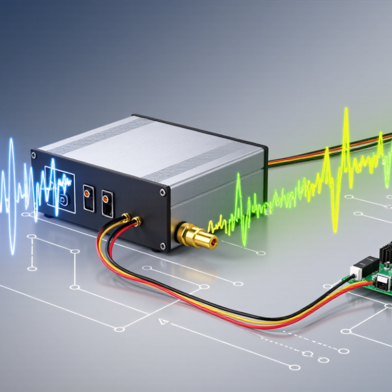
Understand How a Frequency-to-Voltage Converter Works
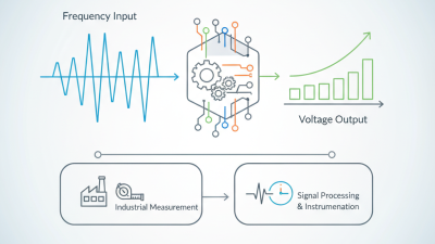
A frequency-to-voltage converter turns repeating input pulses into a proportional DC level. In a common charge-pump design, each pulse transfers a small, nearly fixed amount of charge. More pulses per second mean more average current, which a resistor or filter converts into voltage. At 1 kHz, for example, a circuit scaled to 1 mV per hertz should produce about 1 V. The exact result depends on its components and calibration.
The output is not perfectly steady. A filter reduces ripple, but heavier filtering slows the response when frequency changes. IEC 61000-4-7:2002+A1:2008 uses 10-cycle measurement windows at 50 Hz and 12-cycle windows at 60 Hz, each about 200 milliseconds, for harmonic analysis. That is a useful reminder: measurement windows affect how quickly changing signals appear in a system. One detail matters.
Before selecting a converter, check the full input-frequency range, output-voltage range, pulse amplitude, and expected noise. A sensor may produce narrow pulses at low frequencies, while another source delivers a stronger square wave. Those signals do not necessarily behave alike at the input. I would also check linearity and ripple across the operating range, not just at one calibration point. It is tempting to trust a neat 1 kHz test, but real signals drift, and the filter can hide brief changes.
How to Choose a Frequency to Voltage Converter? - Understand How a Frequency-to-Voltage Converter Works
| Converter Approach | How It Works | Frequency-to-Output Relationship | Strengths | Trade-Offs | Good Fit When | Key Selection Checks |
|---|---|---|---|---|---|---|
| Charge-pump or pulse-area method | Each input edge triggers a fixed charge or a pulse of controlled area. A filter averages the repeated pulses into a DC level. | Ideally, the average output is proportional to input frequency. In a charge-based implementation, the average current is approximately I = Q × f, where Q is charge per pulse and f is frequency. | Simple, naturally produces an analog output, and can provide a useful linear relationship over its designed operating range. | Output ripple and response time depend on the filter. Accuracy can be affected by pulse-area variation, component tolerances, and input-edge quality. | Applications that need a continuously varying analog voltage from a pulse or square-wave signal. | Check input frequency range, allowable ripple, settling time, output span, input threshold, and the linearity and temperature specifications. |
| Monostable pulse averaging | An input edge triggers a one-shot circuit that generates a pulse with a set duration and amplitude. A low-pass filter averages the pulse train. | When pulses do not overlap, the average output is approximately proportional to pulse amplitude × pulse duration × frequency. | Conceptually straightforward and can work well when the input pulse rate and required output response are known. | If the pulse duration is too long for the input period, pulses can overlap and the output may stop being proportional to frequency. Timing components affect accuracy. | Systems with a defined frequency range and enough separation between input pulses. | Verify the maximum frequency against the one-shot pulse width, and check timing stability, output ripple, and recovery behavior. |
| Digital counter with DAC | A timer or counter measures input frequency over a defined interval. Digital processing then scales the result and sends it to a digital-to-analog converter (DAC). | The measured count is related to frequency by the measurement interval; the DAC converts the resulting digital value into a voltage. | Scaling, calibration, and diagnostic features can be implemented digitally. Resolution can be designed around the measurement interval and DAC. | Measurement updates are discrete rather than truly continuous. Longer measurement intervals improve frequency resolution but slow the update rate. | Microcontroller-based systems that need configurable scaling, digital filtering, or additional processing. | Check counter resolution, clock accuracy, input conditioning, measurement interval, update rate, DAC resolution, and output settling. |
| Phase-locked loop (PLL) with filtered control voltage | A phase detector compares the input with a locally generated signal. The loop adjusts an oscillator to track the input; the control voltage can represent frequency within the loop's operating conditions. | The relationship depends on the oscillator tuning characteristic and loop design; it is not automatically a fixed, linear frequency-to-voltage conversion. | Can track changing input frequency and may provide useful filtering of phase or frequency variations. | Loop bandwidth, lock range, capture behavior, and oscillator linearity affect performance. The control voltage may need calibration or additional conditioning. | Applications that already use a PLL or need a tracking response rather than a simple pulse average. | Check lock and capture ranges, loop bandwidth, oscillator tuning range, stability, and the required voltage linearity. |
| Dedicated frequency-to-voltage converter IC | A purpose-designed integrated circuit conditions the input and converts pulse frequency into an analog output, often using internal timing or charge-transfer circuitry. | The transfer function and scaling are defined by the device circuitry and external components; use the specified equations and operating limits from its datasheet. | Can reduce the amount of external circuitry and simplify implementation when its input, output, and performance limits match the application. | Range, supply voltage, output capability, and accuracy are device-specific. External components and layout may still influence performance. | Designs needing a compact analog interface with a straightforward frequency-to-voltage function. | Compare the datasheet's frequency range, transfer-function error, temperature behavior, supply requirements, input thresholds, output drive, and recommended circuit. |
Selection tip: Start with the input frequency range, required voltage span, acceptable error, ripple limit, and response time. These requirements determine whether a simple analog averaging circuit or a digitally measured solution is more suitable. Confirm all numeric limits against the selected circuit’s datasheet and operating conditions.
Related Posts
-
China Top Frequency to Voltage Converter Suppliers?
-
China Top 10 Frequency to Voltage Converter Suppliers?
-

Unlocking Market Trends for Frequency to Voltage Converters at the 138th Canton Fair 2025
-
What is a Frequency to Voltage Converter and How Does it Work?
-
What is a Frequency to Voltage Converter and How Does it Work?
-
7 Best 3 Phase to Single Phase Converters for 2026