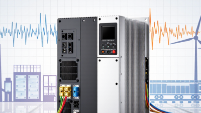
A voltage frequency converter changes electrical power so equipment can receive a different voltage, frequency, or both. In practical terms, it can make a 50 Hz supply operate a 60 Hz motor. It may also adapt voltage for safer, more stable operation.
The device normally uses three stages: rectification, a DC link, and inversion. First, incoming AC power becomes DC through a rectifier. Capacitors then smooth the DC link. Finally, insulated-gate bipolar transistors or newer silicon-carbide switches create a controlled AC output. Pulse-width modulation shapes the waveform. The motor receives adjustable frequency and voltage, allowing controlled speed, torque, and acceleration. It is more precise than simply changing the supply.
The need is substantial. The International Energy Agency’s Energy Efficiency 2023 report identifies electric motor systems as responsible for roughly half of global electricity consumption. The U.S. Department of Energy also reports that motor systems represent more than 70% of industrial electricity use in the United States. Even modest control improvements can therefore reduce energy waste, especially in pumps, fans, compressors, conveyors, and machine tools.
Still, the picture is not perfectly simple. A voltage frequency converter can introduce harmonics, electromagnetic interference, heat, and motor insulation stress. Correct sizing matters. So do grounding, cooling, cable length, and compliance with applicable IEC or IEEE guidance. This article explains the operating principles, main converter types, and practical selection criteria. It also examines a common mistake: treating efficiency claims as guaranteed results. Real savings depend on load patterns, installation quality, and maintenance. Electronics cannot repair a poorly designed system.
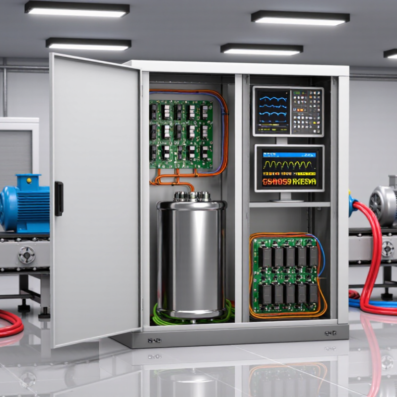
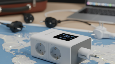
A voltage frequency converter is an electrical device that changes both voltage and frequency. It supplies power in a form that connected equipment can use safely. For example, a converter may accept 230-volt, 50-hertz power and provide a different voltage at 60 hertz. This is useful when equipment and local power systems do not match. A transformer changes voltage only. The converter handles both.
Inside many converters, the input first passes through a rectifier. This stage changes alternating current into direct current. An inverter then creates alternating current again, using controlled electronic switching. Filters help reduce unwanted electrical noise. Control circuits adjust the output voltage and frequency with measured feedback. For motors, this control can influence speed, starting current, and torque. Small changes matter.
The term is not perfectly standardized. Some suppliers use it for motor drives, while others mean equipment for testing or power-system adaptation. That difference deserves checking. In practical work, technicians confirm input limits, output waveform, rated power, and load behavior before installation. A poorly matched converter may overheat, cause unstable operation, or shorten equipment life. Installation should follow applicable electrical codes and qualified procedures. Measurements should confirm the real output, not just the display.
A voltage frequency converter changes the frequency and voltage of alternating current to control the speed and torque of an AC motor. This chart shows an idealized constant-volts-per-hertz profile based on a 230 V, 50 Hz reference: the output voltage increases in proportion to frequency until the rated operating point is reached.
A voltage frequency converter changes incoming electrical power into a controlled output. It can adjust both voltage and frequency for motors, test equipment, and specialized power systems. Its first major component is the rectifier. This circuit converts incoming AC into pulsating DC. Diodes or controlled switches perform this task.
The DC link follows the rectifier. It usually contains capacitors, inductors, or both. These parts smooth voltage changes and store short-term energy. A stable DC link helps the inverter operate accurately. The inverter then rebuilds AC power with electronic switches. It changes switching timing to produce the required frequency and voltage. Pulse-width modulation shapes the output waveform.
The controller acts as the converter’s decision center. It reads voltage, current, temperature, and speed feedback from sensors. Then it adjusts switching signals within milliseconds. Filters reduce electrical noise before it reaches the load. Cooling fans, heat sinks, fuses, and protective circuits manage heat and abnormal conditions. Small details matter here. Field testing may reveal motor hum, unexpected heating, or waveform distortion. These symptoms can indicate poor filtering or incorrect settings. A converter is not perfectly efficient. Switching losses remain, especially at high output frequencies. Engineers should verify grounding, cable length, load behavior, and measurement accuracy before trusting the final setup. Mistakes are possible. A clean display does not always prove clean power.
A voltage frequency converter changes fixed AC power into adjustable AC power. It controls both voltage and frequency for motors, pumps, fans, and test equipment. The U.S. Department of Energy reports that variable-speed control can reduce fan and pump energy use by 20% to 50%, depending on the load and operating profile.
The process begins at the input terminals. An AC filter limits electrical noise and protects nearby equipment. A rectifier then converts alternating current into pulsating DC. Capacitors smooth this DC into a steadier voltage on the intermediate bus. Sensors measure current, voltage, and temperature continuously. Small details matter here. Poor cooling can shorten capacitor life.
Next, switching devices turn the DC bus on and off thousands of times per second. Pulse-width modulation creates a controlled three-phase waveform. The controller adjusts switching timing to set output frequency and voltage. Low frequency usually means lower motor speed. Voltage must also rise carefully, or the motor may lose torque or overheat. IEC 61800-9-2 energy-efficiency data shows that system performance depends on the converter, motor, and driven load together, not on the converter alone.
Protection logic reacts to overloads, short circuits, ground faults, and excessive temperature. Commissioning technicians check phase order, acceleration time, cable length, and motor parameters. The sequence sounds simple. Real systems are less tidy. A claimed 40% saving may disappear when a pump already runs near full speed, so measured field data deserves more trust than a catalogue estimate.
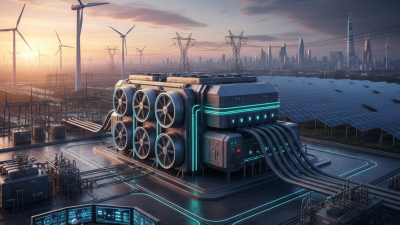
A voltage frequency converter changes incoming voltage and frequency into controlled electrical output for motors and other loads. Its controller samples current, voltage, speed, and temperature, then adjusts switching pulses through power semiconductors. The International Energy Agency’s Renewables 2024 report forecasts nearly 5,500 GW of new renewable capacity by 2030. That expansion increases the need for converters that can manage fluctuating power and variable operating conditions.
The simplest control method is scalar V/f control. It maintains a voltage-to-frequency ratio, making it economical for pumps, fans, and conveyors. Sensorless vector control estimates rotor position from electrical feedback. It provides faster torque response without a physical speed sensor. Closed-loop vector control adds an encoder, improving low-speed accuracy and load stability. U.S. Department of Energy motor-system assessments identify motor-driven equipment as a major industrial electricity consumer, so small efficiency gains can become significant.
Operating modes should match the mechanical load. Variable-torque mode reduces speed and power for centrifugal fans and pumps. Constant-torque mode supports conveyors, mixers, and hoists. Regenerative mode returns braking energy to the DC bus or supply, when the system permits it. Bypass mode can maintain operation during converter faults, but it reduces control flexibility. Real commissioning is less tidy. Cable length, grounding, motor age, and incorrect acceleration settings can create faults. A converter may be technically correct yet poorly matched to the site. Measurements matter.
A voltage frequency converter changes an AC supply’s voltage, frequency, or both. It can convert 230 V at 50 Hz into 120 V at 60 Hz, depending on the equipment and application. Inside, the unit usually rectifies incoming AC, controls the electrical signal, and creates a new output waveform. The result should match the connected load, not merely the wall socket.
These converters support motor testing, industrial machinery, laboratory equipment, medical systems, and international product testing. A motor may run more smoothly when supplied with its rated frequency. Sensitive equipment can also benefit from regulated voltage and reduced electrical disturbances. However, benefits depend on correct sizing. A converter rated for 2 kVA may struggle with a motor that briefly draws three times its running current. That detail is easy to miss.
Selection requires more than checking input and output voltage. Confirm frequency range, phase type, continuous power, surge capacity, waveform quality, efficiency, cooling, and protection features. Motors may need a higher starting allowance. Electronic loads may require a low-distortion sine wave. Installation space and ambient temperature matter too. In a warm control room, poor ventilation can shorten service life. A practical choice is rarely perfect. Testing the actual load remains wiser than trusting a specification sheet alone. Safety certification and qualified electrical installation should also guide the final decision.