
What Is an AC to AC Inverter and How Does It Work?
An ac to ac inverter changes one alternating-current supply into another form of alternating current. It can adjust voltage, frequency, phase, or waveform to match a machine’s operating needs. Unlike a basic transformer, it does more than raise or lower voltage. It actively controls electrical power.
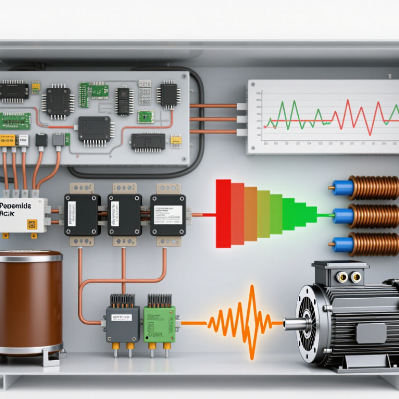
Most modern designs use a two-stage process. The incoming AC first passes through a rectifier and DC-link capacitor. Power switches then recreate AC through rapid pulse-width modulation. Filters smooth the output before it reaches a motor, appliance, or grid-connected system. Some advanced converters use matrix-converter technology for direct AC-to-AC conversion.
The control board acts like a careful conductor. It monitors current, voltage, temperature, and switching timing. A variable-frequency drive, for example, may slowly increase motor frequency to reduce starting stress. The motor then accelerates smoothly instead of producing a harsh electrical surge.
Real hardware is less perfect. Switching creates heat, electromagnetic noise, and small waveform distortions. Component tolerances also affect performance. An oscilloscope may reveal ringing that a simple calculation misses. Engineers therefore check datasheets, thermal limits, insulation ratings, and protection functions before selecting an inverter.
This article explains how an ac to ac inverter works, from input conditioning to output filtering. It also examines common circuit types, practical applications, efficiency limits, and safety considerations. The terminology can feel confusing at first. Clear measurements make it manageable.
What an AC-to-AC Inverter Is and What It Controls
An AC-to-AC inverter changes one alternating-current supply into another with controlled electrical characteristics. It may adjust voltage, frequency, phase, or waveform shape. Many units first convert AC into DC, then create a new AC output through electronic switching.
The main control is frequency. A motor usually spins faster when output frequency rises, while lower frequency reduces speed. Voltage control helps maintain suitable torque and limits excessive current during acceleration. The inverter can also manage phase timing, allowing smoother motor operation and better synchronization with the load. Pulse-width modulation shapes the output by switching rapidly. A filter then reduces unwanted electrical ripple.
In practical testing, I check the input and output with suitable meters and an oscilloscope. Motor sound, vibration, and temperature provide useful clues too. A stable display does not always mean a clean waveform. That difference matters. Poor settings can cause overheating, weak torque, or unexpected shutdowns. Protection functions may monitor overcurrent, overvoltage, short circuits, and excessive temperature. However, these functions are not a substitute for correct installation or careful parameter selection. I have found that small frequency changes can produce noticeable mechanical effects, especially in pumps and fans. The term “inverter” can also create confusion, because AC-to-AC designs use different circuit structures. Reviewing the actual conversion method is essential. Small errors matter.
| Data Dimension | Typical Value or Classification | Technical Description |
|---|---|---|
| Definition | Power-electronic AC-to-AC converter | An AC-to-AC inverter converts an alternating-current input into an alternating-current output with controlled voltage, frequency, phase, or waveform characteristics. In industrial systems, the term commonly refers to a variable-frequency drive or another frequency converter. |
| Input Power | Fixed-frequency AC | The input is usually single-phase or three-phase utility power. Common nominal systems include approximately 120 V, 230 V, 400 V, or 480 V AC, depending on the electrical installation. |
| Output Power | Controlled AC | The output remains alternating current, but its voltage, frequency, phase angle, and waveform can be adjusted to match the requirements of a motor, grid interface, heating load, or other equipment. |
| Main Conversion Method | AC–DC–AC indirect conversion | A widely used topology first rectifies the incoming AC to DC, smooths the DC-link voltage with capacitors or inductors, and then uses semiconductor switches to synthesize a new AC output. |
| Direct Conversion Method | Cycloconverter or matrix converter | Direct AC-to-AC topologies transfer energy without a conventional DC link. They can provide bidirectional power flow, but their control and filtering requirements are generally more complex. |
| Rectifier Stage | Diode, thyristor, or active rectifier | The rectifier determines how the input AC is converted to DC. A diode bridge is simple and economical, while an active rectifier can improve power factor and allow regenerative energy to flow back toward the supply. |
| DC-Link Function | Energy buffering and voltage smoothing | The DC link reduces ripple between the input and output stages and provides a stable energy reservoir. Capacitor-based links are common for voltage-source inverters, while inductive links are used in selected current-source designs. |
| Switching Devices | Power transistors or thyristors | Insulated-gate bipolar transistors, metal-oxide-semiconductor field-effect transistors, silicon-carbide devices, and thyristors may be used according to voltage, current, switching-frequency, and efficiency requirements. |
| Output Switching Method | Pulse-width modulation | PWM rapidly switches the output devices and varies the pulse widths to approximate a sinusoidal voltage or current. A motor's inductance and an external filter help smooth the high-frequency switching components. |
| Frequency Control | Adjustable output frequency | The controller changes the switching pattern to set the fundamental output frequency. Lower frequency generally reduces AC motor speed, while higher frequency can increase speed if the motor and mechanical system are rated for it. |
| Voltage Control | Adjustable output voltage | The modulation index controls the fundamental output voltage. For induction motors, the controller often maintains an appropriate voltage-to-frequency relationship to preserve magnetic flux and usable torque. |
| Phase Control | Phase angle and phase sequence | The inverter controls the relative timing of the output phases. Changing phase sequence can reverse motor rotation, while phase-angle control influences torque, power factor, and synchronization behavior. |
| Waveform Quality | Synthesized near-sinusoidal fundamental | The switched output contains the desired fundamental component plus high-frequency harmonics. Motor impedance, output reactors, or dedicated filters can reduce ripple, acoustic noise, electromagnetic interference, and voltage stress. |
| Control Strategies | V/f, vector control, or direct torque control | Scalar V/f control is relatively simple. Vector-oriented methods independently manage flux and torque for faster dynamic response. Direct torque control adjusts switching states using torque and flux feedback. |
| Feedback | Open-loop or closed-loop | Open-loop control estimates operating conditions without a speed sensor. Closed-loop systems use feedback from current, voltage, speed, position, or torque sensors to improve regulation and dynamic performance. |
| Motor Speed Relationship | Primarily determined by output frequency | For an AC motor, synchronous speed is related to frequency and the number of magnetic poles: synchronous speed in revolutions per minute equals 120 multiplied by frequency in hertz, divided by the number of poles. Induction motors operate slightly below synchronous speed because of slip. |
| Power Flow | Usually one-way; bidirectional when designed for it | A standard diode-front-end converter normally delivers power from the AC source to the load. Regenerative braking and four-quadrant operation require an appropriate active front end, braking circuit, or other energy-return arrangement. |
| Common Applications | Motor drives, pumps, fans, compressors, conveyors, and test systems | Adjustable AC output allows equipment to match speed and torque to the process. This can improve process control and reduce energy use in variable-torque loads such as fans and centrifugal pumps. |
| Key Benefits | Speed control, soft starting, and improved process control | The converter can limit starting current, provide controlled acceleration and deceleration, maintain a desired operating point, and support protective functions such as overcurrent, overvoltage, and thermal monitoring. |
| Main Limitations | Harmonics, switching losses, and electromagnetic interference | The rectifier can distort the input current, while high-frequency switching can create conducted and radiated emissions. Proper grounding, shielding, filtering, cable selection, cooling, and parameter settings are important for reliable operation. |
| Efficiency Consideration | Less than 100%; depends on topology and load | Losses occur in the rectifier, DC-link components, switching devices, conductors, filters, and cooling system. Efficiency generally varies with load level, switching frequency, output frequency, and operating temperature. |
| Protection Functions | Overcurrent, overvoltage, undervoltage, overheating, and ground-fault protection | Control electronics monitor electrical and thermal conditions and can block switching or shut down the converter when unsafe limits are detected. Protection settings must be coordinated with the source, load, wiring, and application. |
| Important Note | An AC-to-AC inverter does not necessarily increase or decrease voltage in the same way as a transformer. Its primary function is electronic control of AC power characteristics. The exact input range, output range, topology, and performance depend on the converter design and its rated load. | |
Related Posts
-
Top AC to AC Inverters for Global Buyers
-
2026 Best AC to AC Inverter for Global Buyers?
-
What is a 3 Phase Frequency Converter and How Does it Work?
-
What is a 3 phase frequency converter and its benefits?
-
10 Best 3 Phase Frequency Converters for Global Buyers
-
What Is a Voltage Frequency Converter and How Does It Work?